Power series:
|
150 kW – 180 kW – 199 kW – 220 kW – 250 kW
300 kW – 350 kW – 400 kW – 450 kW – 499 kW – 500 kW
|
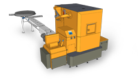
The boilers are predominantly supplied with a so-called central fuel extinguishing device which automatically feeds in the fuel from the central warehouse to the boiler’s intermediate container (USZI). Alternatively, the boiler may be installed with a 1-1.4 m3 volume fuel container (USV). With account taken of the capacity of the boiler container, it is recommended for the present modification to further automate the supply of fuel (such as in combination with a silo). A screw conveyor is used to feed the fuel to the high-temperature combustion chamber, where it is ignited automatically. It burns out on a circular burner while primary air is fed in. The two-part secondary crown of additional combustion with secondary and tertiary air supply located above it provides for the full combustion of the emerging gases. Full combustion is supported by the deflector located above the combustion chamber, which also adequately rectifies the direction of the flue gases prior to their entry into the heat exchanger.

The same is located above the hearth, and its heat transfer surfaces are cleaned automatically. That guarantees high efficiency of the system. Optimal flow of the flue gases is ensured by an exhaust with continuous control as a function of the actual underpressure in the combustion chamber, which is continually read. For boilers falling into this power series, the exhaust fan is part of the separator of solid pollutants (cyclone). Once burnt out, the ash is carried into the ash pocket using two feed screws. The function of the entire boiler is controlled by a control unit, which allows for setting the required mode for each fuel used and simultaneous two-way communication via a GSM modem, which may be visualised. The control unit optimises the combustion process across the entire range of power of the boiler by continually monitoring the oxygen surplus values by a lambda prove in the flue gases. That guarantees the high efficiency of the facility across the entire range of controllability. Boiler power may be controlled within the range of 30 to 100%.
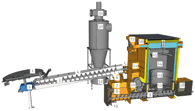
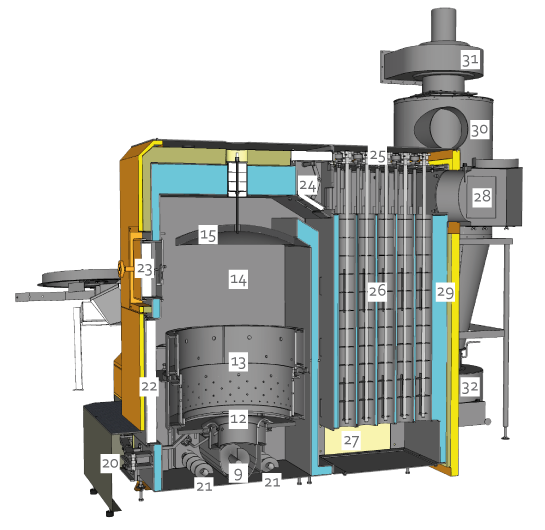
Large-series boiler cross section
Explanation:
| 1. |
Spatial staging motor |
| 2. |
Stirrer screw gear box |
| 3. |
Conveyor screw |
| 4. |
Fuel conveyor |
| 5. |
Conveyor motor and gear box |
| 6. |
Flap separating intermediate container and conveyor |
|
| 7. |
Intermediate fuel container |
| 8. |
Disrupting mechanism |
| 9. |
Feed screw |
| 10. |
Accessories
– Primary fan
– Secondary 1 fan
– Secondary 2 fan
– Igniting fan
– Emergency extinguishing device |
|
| 11. |
Control panel with control system |
| 12. |
Primary burner with a moving grate |
| 13. |
Two-part secondary crown of additional combustion |
| 14. |
Combustion chamber |
| 15. |
Deflector |
| 16. |
Servo-drive of heat exchanger flap |
| 17. |
Turbulator drive motor |
| 18. |
Ash pocket |
| 19. |
Feed screw motor |
| 20. |
Grating mechanism with a motor |
| 21. |
Ash screws |
| 22. |
Service boiler door |
| 23. |
Inspection boiler door |
| 24. |
Exchanger flaps |
| 25. |
Tabulator drive |
| 26. |
Heat exchanger with turbulators |
| 27. |
Exchanger service door |
| 28. |
Chimney extension |
| 29. |
Dual boiler insulation |
| 30. |
Separator of solid pollutants |
| 31. |
Exhaust fan |
| 32. |
Separator ash container |


